What a Printer Carriage Has to Read
The thin strip behind a moving inkjet carriage helps it keep track of where it is. A skewed line on a page can come from that reference, the way the paper moves or several other causes.
In this story 5 sections
A printer draws a vertical line using movements that do not look vertical at all. In a common inkjet arrangement the carriage travels sideways, while the sheet advances in another direction. Marks left in successive passes have to meet. If one group lands slightly to the right of the last, the line that was straight in the file can step on the page. Some part of the printer has to know where the carriage is along its journey, even though the person waiting for the page sees only the tray.
HP describes an encoder strip on a number of Designjet printers for this purpose. The strip is partly transparent, and in those machines it runs near the carriage rod. It can be easy to miss in a view of the open case. The rod helps guide a part that moves; the strip gives the sensing system a reference for that movement. Looking at a guide rod alone tells you very little about how a printer decides when a nozzle is in the right place.
Motion and information take parallel routes
Think of a simple moving part on a track. A motor can be commanded to move it. That command does not by itself show that the part actually reached the intended position. Mechanical resistance or loss of motion can leave the result different from what was asked. To see the value of feedback, distinguish the command, the motion and a measurement taken as it happens. Printing relies on bringing mechanical motion and timed marks together.
An optical linear encoder can make movement legible by using regularly spaced markings on a strip and a sensor that passes them. In a simplified model, the sensor records repeated changes between lighter and darker parts. A controller can keep track of movement using those changes. That is similar in purpose to counting ticks on a ruler while it slides past a fixed point, although real devices may use more than one signal and more complicated reference arrangements. What matters is that one mechanical path carries a position reference.
A row of equally spaced marks does not put a unique address on each mark. If you look at one segment in isolation, you may not know whether it belongs near the middle or near an end. An incremental position system needs a starting reference and a way to keep track of changes, or some other way to establish where movement begins. Exact homing arrangements differ. The important distinction is that recognizing movement along the scale and establishing a position in the printer's working range are related but different tasks.
How a straight line turns into steps
Imagine a printer with a head that is supposed to start placing one row of a pattern at a particular point. Its mechanical guide is still straight. Suppose the position estimate is off slightly for one pass. The drops can land in a row as neatly as before and still be shifted against the preceding row. A straight diagonal or a thin vertical edge can make the shift easy to see. In a dense photograph the same fault could initially be noticed as a narrow disturbance rather than a clearly displaced line.
HP's support article lists vertical flaws, shifted margins and shadowed lettering among the possible symptoms for its specified Designjet series when material builds up on the encoder strip. It also cautions against treating unrelated problems as evidence of a dirty strip. The list is a useful published example, not a universal diagnosis for every desktop or large format printer. Other designs and other combinations of symptoms require their own manuals and checks.
One thing a person inspecting an output can record is where the fault appears relative to the paper. Perhaps a narrow flaw recurs at the same distance from the left edge even when the printed rectangle is moved. Perhaps the flaw follows the graphic instead. The first pattern can point attention toward something about that location in the machine; the second can justify checking the artwork and print settings before opening covers. Neither observation is quite enough to identify a failed component by itself.
Paper has a journey of its own
The sheet generally moves across a second axis. A problem with feeding can cause its own gaps, overlaps or changes of position. An empty stretch on the page need not come from the same mechanism as a left margin that moves sideways. A blockage, a wrong paper setting or a sheet loaded badly should not be blamed on an encoder merely because both problems can leave an unattractive print. The direction of the flaw and the operating circumstances help narrow the question.
A simple test image can be more useful than the complicated document that first exposed the problem. A small page from the printer's own diagnostics, if the model provides one, reduces the number of things between the intended pattern and the output. Compare its orientation with the flawed page and note the print mode used. A built-in test that shows the same symptom suggests that the original application was not required to reproduce it. It still does not determine why the machine made the mark.
A missing nozzle is yet another possibility in an ink delivery system. A useful comparison distinguishes an area in which planned ink is absent from an area in which the ink appears to be displaced. That difference can be hard to establish without a known test figure. A support guide designed for the model is a better source for interpreting its diagnostic patterns than a photograph clipped out of an article about another printer.
Why an ordinary dusty area is not a useful diagnosis
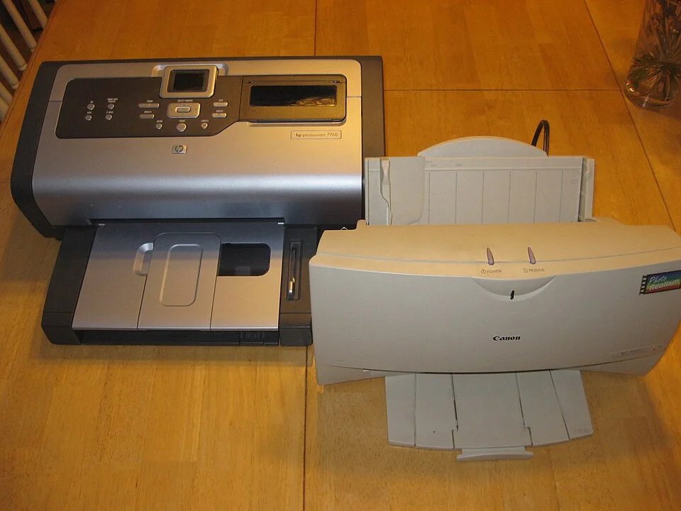
The inkjet printers photographed here are shown from the outside. There is no visible evidence about whether either one's internal scale is clean. That matters because a printed page and a case opening each give partial information. Somebody may see dust on one surface and attribute every visible flaw to it. Another person might notice nothing unusual and dismiss a problem in a small part of the machine that is hard to inspect. Both are shortcuts around the actual relationship between a sensor and its reference.
The strip is functional artwork at the scale of the printer. The markings have to be in a predictable place when the detector reads them. Bending it, contaminating it or disturbing its mounting can make the job harder. When a manufacturer publishes a procedure for machine care, use the guidance for the exact model and the condition it identifies. Some procedures specify particular areas and materials and warn against applying the same treatment to a neighbouring part. For a machine outside the scope of the document, the fact that a component looks familiar is not sufficient.
A good record can make service simpler. Save a sheet or a scan of the fault with the feeding edge marked. If it recurs intermittently, note which modes or kinds of paper were in use. Record whether a built-in diagnostic also shows it. Those are better starting points than ordering a replacement part based on an external view of the printer. They help a repairer work backward from a repeatable mark to the sequence that may have produced it.
A motor and a ruler solve different problems
It can help to draw a hypothetical row with marks at zero, two and four millimetres. If a controller misses one two millimetre interval, the numbers it believes it has passed can lag behind the physical position. If instead the sensing works and the sheet slipped forward, the same points can exist along the carriage path without falling where they were meant to land on paper. The invented dimensions do not describe any printer. The comparison shows why looking for signals in one direction can be useful and still fail to explain motion in another.
A mark that is different when the carriage approaches from the opposite side can raise another question. In a design that prints in both directions, the two passes must agree about where to put a shared edge. Even with a reliable position reference, timing and calibration can matter to that agreement. A model may provide an alignment check for this reason. Its instructions and the result of its own pattern are better evidence than trying to identify the sense of the carriage's travel from a single printed edge.
What is striking about the carriage is that a great deal of physical work can be visible while its most useful reference is almost invisible. The drive makes the sweep. The guide holds the carriage to a path. A sensing system makes the path measurable in motion. The control logic has to turn that measurement into the timing of separate dots. If two of those stages do not agree, the page can show the disagreement with a nudge at the end of a line.
Approach the evidence in that order the next time a vertical mark begins to stair-step. First ask whether it is printed where it was intended, then whether the shape is intact, and then which other jobs the printer had to do for one pass to meet the next. If the model documents an encoder strip, there is a reason it sits near the carriage but does not carry it. The distance between those two parts is a compact lesson in the difference between moving to a place and knowing where you arrived.