The Short Turn That Locks a Camera Lens
A bayonet mount has to support a lens and put it in a repeatable position. A match in diameter is only the first clue to whether a body, lens and adapter work together.
In this story 5 sections
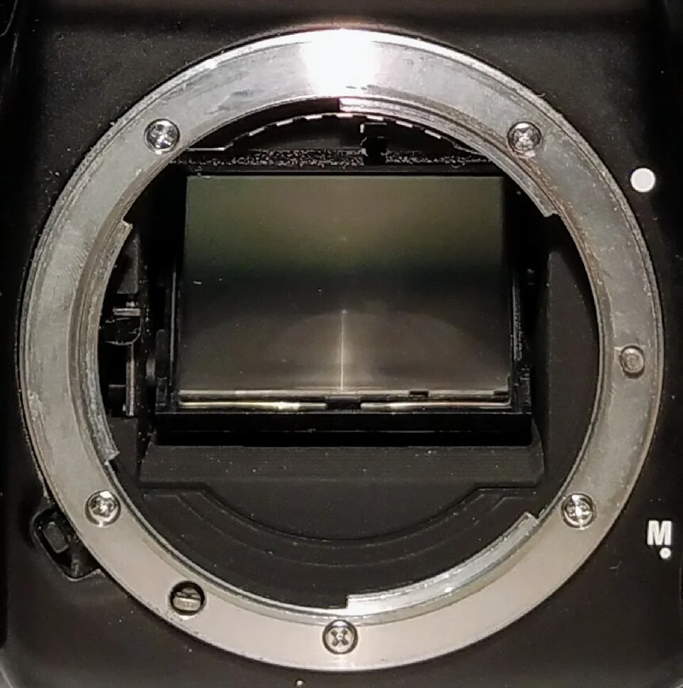
The open front of the camera in this photograph looks like a nearly perfect circle with interruptions at the edge. A lens has to use those interruptions. It is introduced at a defined alignment, then turned a short way until the body and lens are held in a position they can return to again. The job looks simple enough to forget after attaching a few lenses. The instant a lens is uncertain on the body, some of that simplicity reveals itself as a series of exact requirements.
Nikon describes its F mount DSLR procedure in terms of aligning marks, seating the lens and rotating it until it locks. That is a direct statement about the design and procedure covered by its instructions. Other systems can have different orientations and release arrangements. The Nikon F50 photograph shows the visible mount on an F-series film camera. It lets us examine the rough geography of the joint while the instructions and model information answer the more specific questions.
One movement places the lens; another retains it
In a simplified bayonet arrangement, projections can enter through openings when the two parts are aligned. A short turn takes them away from those openings and into a position where the parts overlap and are held together. Retaining the final position is a separate task. The stop or lock keeps a lens from drifting back to the insertion angle in ordinary use. A close fit without an engaged lock can be a different state from a lens fully attached.
Think of how this differs from a long screw thread. A bayonet arrangement trades repeated turns for a controlled insertion and a short rotation. It also has a clearly defined orientation. If the notches are not lined up, the lens cannot start in the same way. Trying to turn a lens that has not seated can make force feel like progress when something does not fit. The markings and the expected action exist precisely to let the user distinguish those cases before applying more effort.
A release control does another job. It lets a person take a properly attached lens back to the position from which the parts can be separated in the intended manner. The ability to release a lens on demand and the ability to keep it still during a photograph are not opposites that have to be traded directly against one another. They are achieved by successive states of the same connection. An instruction manual explains which state the user is trying to reach at each step.
Distance is as important as diameter
The lens does not merely need to face the camera. The body and lens have a designed relationship to the film or sensor plane. The distance from a mounting reference to that plane is often described as a flange distance. An adapter or mounting arrangement that changes the geometry can affect the conditions under which a lens focuses as intended. Two circular openings that appear similar in photographs do not establish that this distance, or the rest of the design, is the same.
Here is a useful visual model. Draw the image plane as a line in the body and a second line at the mounting face. The space between those lines belongs to the camera's design. A lens attaches outside that reference, but its focusing was worked out in relation to the system as a whole. An adapter has to fit between two sets of mounting features while preserving the relevant optical geometry as designed. A simple ring that joins two circles is not evidence that it does both jobs.
A mirror camera can add other questions about room behind the lens. In the cover photograph the mirror is visible within the opening. The visible room is not a guide to which parts are allowed to extend into it under operation. For that, consult documented compatibility of the particular body, lens and any adapter. Similar size suggests a possible comparison, not permission to test what a manufacturer explicitly excludes.
Fitting and communicating are separate tests
An interchangeable-lens system can use electrical contacts, mechanical links or a combination for functions besides holding the lens. Depending on the design, a body and lens may exchange information or support features such as automatic focusing or exposure-related control. A lens may be able to sit on a compatible adapter while some functions remain manual. Whether that matters depends on what the photographer needs the system to do.
Nikon's description of its FTZ and FTZ II adapters illustrates the difference. It identifies F-mount lenses that can be used on its Z-series bodies under different conditions and describes compatibility for particular groups, including groups that retain fuller automatic functions. The exact category and models matter. An adapter described as useful for one group does not turn every function of every older lens into a feature available on the new body. The most useful comparison is a specific combination and a specific function.
For example, imagine someone who wants to use an older lens for a still subject and expects to focus manually. Somebody else hopes to record a moving subject using autofocus. They could both ask if the same lens works on the same body and actually need different answers. Start by naming what must work: attachment, a particular focus mode, exposure information or another feature. Then consult the documentation for that exact arrangement. The word compatible is more informative when it says what it is compatible for.
Read a loose joint before deciding what is loose
Movement can happen in several places. A lens assembly can have moving rings or parts that normally travel; a body or adapter can have a separate mounting surface. A complaint that the lens moves can refer to a control turning as designed or to movement at an interface that should remain secure. Record where the movement begins and which pieces move relative to each other. A visible gap, a change after a fall or a lock that no longer engages is more useful evidence than a broad conclusion from an unfamiliar feel.
When the fit is in doubt, check the relevant user instructions and do not force the parts. A repair estimate or manufacturer check can distinguish a problem on the body from one on the lens or adapter. Comparing a documented combination in good order may help a repairer find which part is involved. The comparison should not require somebody to improvise a test with an apparently similar mount. What one ring happens to resemble is seldom the issue that needs repair.
The opening in the photograph is the start of the story
There is another relationship worth distinguishing when a joint feels wrong: the one between the location of the mount and the load it is being asked to carry. A short, light lens and a long assembly containing heavy glass may impose different turning effects on the same body joint. The position of that weight matters as much as the number printed on a scale. Some lens designs provide their own support point. Where one is documented, that information belongs in a comparison of equipment rather than assuming the area around the body's mount is always the intended point to support the entire assembly.
A person can compare two situations without connecting unfamiliar parts. In the first, a lens seats with the expected action but the camera does not report a function the user expected. In the second, the lens encounters an unexpected stop before it engages the lock. The first observation leaves room to investigate whether the function is supported or whether a contact has a fault. The second raises a mechanical question first. Treating the two as failures of the same general property called compatibility discards the separate evidence each observation offers. The first safe inquiry is which explicit combination the manufacturer documents and which stage of attachment actually succeeded.
A mounting reference can be useful even where the lens has no contacts at all. A purely mechanical lens still needs repeatable alignment. Its position controls how light meets the image plane, even though the user may control focus and aperture without involving the camera electronics. Conversely a visible block of contacts in a mount can confirm that the design is prepared for certain communications without proving that a body and lens will recognise each other. Geometry and supported functions are deliberately separate columns on a good compatibility reference.
The picture itself illustrates another kind of limit: the circular edge is much easier to compare at one magnification than its small locking and signalling details. If you document a fault, add a view wide enough to identify the body as well as any useful close view. Keep part names or model references in the report. That makes it possible to compare the actual interface with documented examples rather than only compare metal shapes.
Look at the lip of the mount and the gaps interrupting its outline. They give the most immediate clues that the lens enters in one orientation and ends in another. The image does not show the whole connection once the lens is attached. That is when seating, the lock, any electrical contact and the resulting focus condition start to do their work. A short turn is how someone reaches that position. Whether it was the right position depends on the design of both sides of the joint.