The Latch on a Flat Flex Cable
Some of the thinnest cables in a laptop depend on a tiny moving piece in the socket. Identifying what that piece does is more useful than judging the cable’s strength.
In this story 4 sections
Before a flat cable comes free of a small socket, one thing on the socket may need to move a remarkably short distance. Guess wrong about what that thing is and the cable can seem stuck. Guess again, using a little more force, and part of the board or connector can break long before the cable moves usefully. This is one of the cases in a computer repair in which skill often looks like doing nothing for a moment. Take a clear look at how the two pieces are attached. There is time to think before anything has to be adjusted.
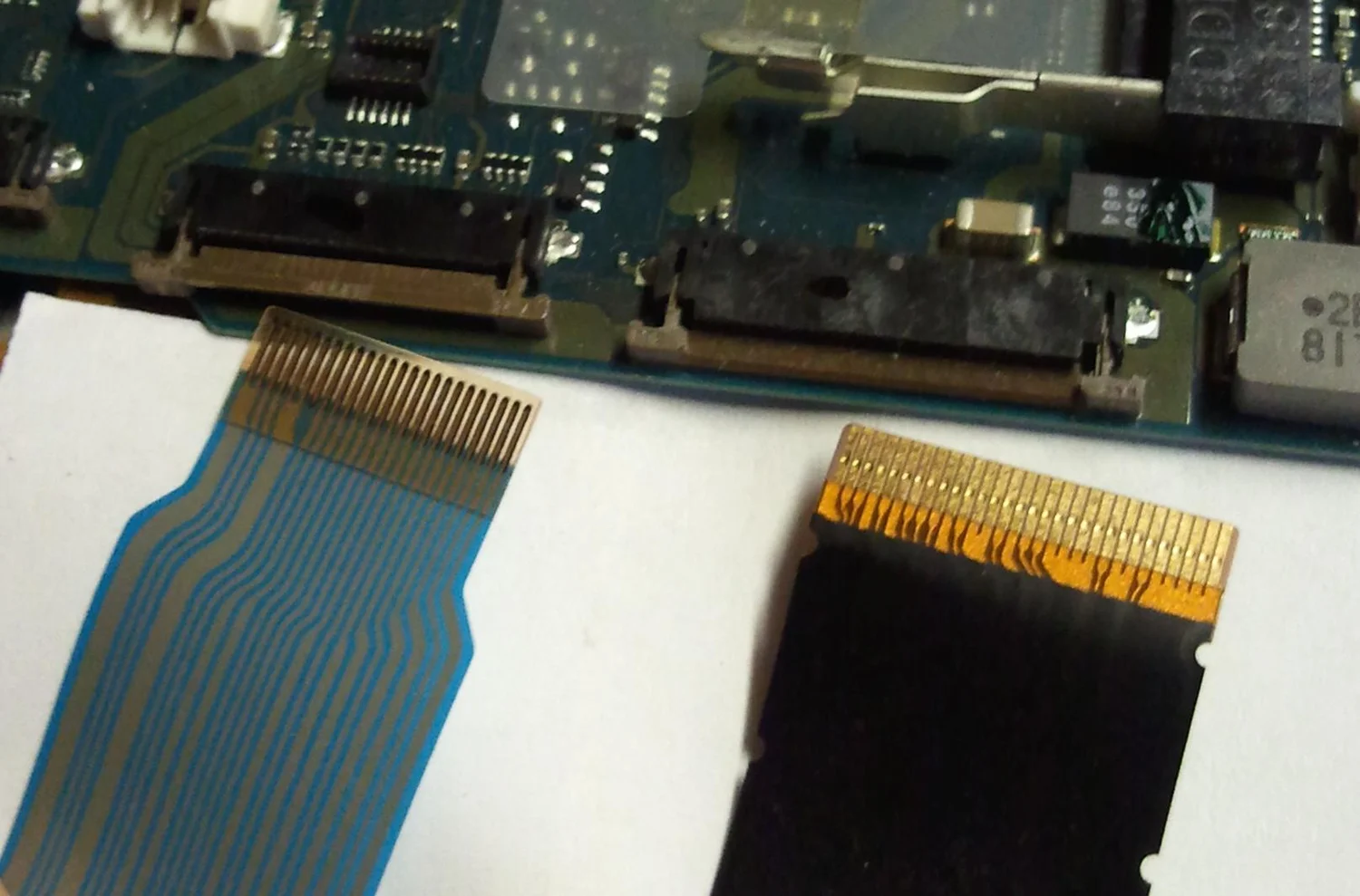
A flat flexible cable puts several conductive paths next to one another in a thin assembly. In a laptop it might connect a nearby part to a board without needing much space above the surface. The photo here shows flat cables and two sockets on such a board. What looks like a simple slot may have to do at least two things: place the contacts together and keep them in their intended relationship while the surrounding device is handled. The control that changes between positions can be no wider than the cable.
Start by naming the possible pieces
A cable using a zero insertion force connector is intended to fit when a particular mechanism is open without the force it would take to meet the contacts in the operating position. An actuator can then secure the cable and bring the parts into their proper working relationship. The principle is easy to say and hard to apply by appearance alone. Small connectors can use different designs. Some have a part that pivots. Some have a latch that slides. Some similar-looking connectors are held by friction or use a different retention method. There is no useful rule that every dark plastic strip can be lifted from the top.
Identify the fixed housing, the cable and any part the documentation describes as movable. An ordinary photo of a complete assembly may show only two of the three. If you can find the exact service guide or connector documentation, follow the descriptions for that part. The iFixit guide illustrates several mechanisms, which makes a useful comparison when you are trying to learn what not to mistake for a latch. Do not make a closer match than the evidence supports. A part can have the same colors and a different action, especially when you only see its front edge next to the inserted tape.
A good independent clue is where the cable enters. Look along the board and see whether the cable ends in a horizontal slot or elsewhere. If the cable runs towards a part from one side, that tells you where contact is likely to occur. It does not tell you which part of the connector moves. A component soldered to the board should not start moving because you have decided it resembles a hinge. If you cannot identify the release, stop at observation instead of trying one edge after another. The cost of a second photo is almost always lower than the cost of a broken socket.
The cable can be right side up for one socket only
Seen from above, a ribbon of this kind can have a uniform color across most of its length. Its terminal end can reveal the contact area on one face. Some connectors are designed for contact on the top, some on the bottom, and some mount in other positions. Hirose’s catalog gives such variants within one family of connectors, including versions that may look similar in a photograph at a different angle. The interface between cable and housing is more specific than the fact that the tape physically fits through the opening.
Before disturbing a connection in an appropriate, fully powered-off repair, record which face of the cable is visible and where any alignment marks, reinforcing tab or ends appear relative to the slot. The manufacturer’s disassembly and safety instructions should govern the operation, including how a battery is dealt with on the actual device. Your record does not replace the instructions. It preserves features of the initial state that the instructions might identify by a different viewpoint or by details that are hard to recognize after the cable has fallen flat.
Observations should be specific. “Blue end facing up” can work for a particular cable if the blue backing is unique and the point of view is clear. A few weeks later the same sentence can be very ambiguous if it could refer to either end or if the other side of the board is visible in another image. “Blue backing visible looking down at the side marked by the fan” is closer to an instruction someone can check. Photograph an overview as well as the close-up so that you do not have to use unrelated background details to put the picture in the correct orientation.
A connector is small; the change it permits is specific
Picture a removable card guided into a wider desk slot. It can enter with little scraping if the path is left clear. Now imagine a separate part that applies a gentle clamping action once it has reached a defined position. If the desk slot were a tiny electrical connector, it would need to hold many points of contact in alignment. A tool applied to the wrong edge can change forces well away from the contact strip. Being unable to see the movement easily does not justify applying more force. The thing to observe is the degree and direction of movement the design intends a part to have.
A cable that goes in at an angle may not line up all of its contacts at the same time. A reinforcing tab on the end is typically there for a particular mechanical purpose. It is not a general handle by which the cable can be peeled away from the board. The cable can also be attached elsewhere to guide or support it. In a service drawing, trace the route as well as the end, and see whether tape, clips or bends can affect the small bit of movement available. Working at one end without understanding how the route is held can put strain far away from the socket you meant to work with.
The photo of two connectors is especially useful for this reason. Their presence on one board does not establish that the cables can swap places. Pitch, number of contacts, contact face, availability of space and the connection beyond the slot are separate facts. A replacement cannot be chosen simply because its width looks similar in a crop. If it belongs to a named assembly, confirm the part identification in the service information. In a photographic comparison, keep separate observations of the intact mechanism and whatever you can learn about the actual electrical use of the connection.
Some connectors look similar from above because the fastener is almost entirely hidden in the open or closed position. A sideways view can show a gap or a different relation between the moving part and the housing. If the part you need to identify lies under another assembly, let that restriction remain part of the diagnosis. A guess made with reduced visibility is still a guess. An appropriate service guide may explain how to expose the part without disturbing it, or may identify a connector intended to be replaced only as part of a larger assembly. That difference can change whether a job can reasonably be attempted with the information you have.
Diagnose the result at the scale you can support
If a device no longer recognizes a component after a service task, a disconnected cable is one candidate explanation. It is not proof that a particular contact was damaged. You can compare against the earlier photographs and approved instructions without repeatedly opening and closing a connector in the hope that the symptom disappears. Record whether any other parts were changed and whether the symptom was present before beginning. Test in the intended state of reassembly and according to the service guidance for the equipment, not by touching an open powered board to see if the symptom changes.
A broken actuator can leave a cable looking as though it is fully present. There may still be no proper retention or contact pressure. Tape stuck elsewhere can make the outside of an area look stable without restoring what the socket was designed to do. An appropriate repair then depends on what has actually failed and what the manufacturer or an experienced repair shop can support. This is one of the costs a clear first inspection is trying to avoid: by the time the fixture itself is broken, the problem belongs to a board, not simply to a removable line.
If you are learning by looking at photographs, find a pair of views of a known socket open and closed. Identify what shifted relative to the stationary housing. Then find a different example and ask yourself exactly where your observation stops transferring. Learning one small interface well develops a habit more useful than memorizing a series of pretend steps for all laptops. A connector can be designed to make a particular movement surprisingly easy. The work is recognizing which movement makes sense for that connector before your tools create another one.