Why a Fiber Has a Bend Radius
A bend can reduce the light delivered by optical fiber even if the glass is intact. The useful specification belongs to the whole cable and the way it is installed.
In this story 4 sections
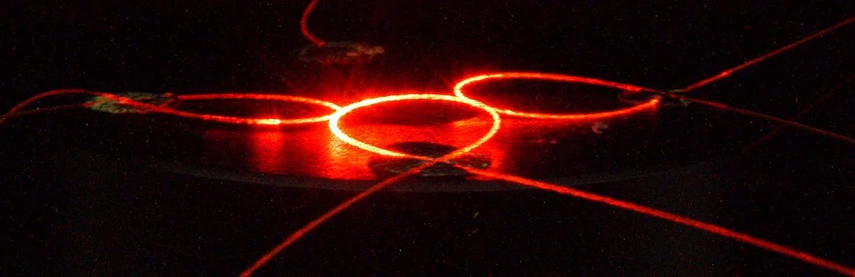
A copper wire makes the idea of a broken cable easy to picture. Leave a gap and the conductive path ends. Optical fiber can frustrate the same intuition. A path made from continuous glass can deliver less light when parts of it curve too sharply. You do not necessarily see a break in the material or any other change in the outside of the jacket. In a laboratory demonstration you may be able to see light leaving a bend, as in the photograph by Christophe Finot. In an ordinary data link you may instead find an indication of reduced received power, an error count or a connection that does not come up at all.
The useful thing to ask of a fiber around a corner is how much room the corner gives it. A broad arc can be perfectly normal. A tight turn tends to be more demanding, and the limit for a given cable depends on the assembly and how it is being used. It can be confusing to find several apparently conflicting bend specifications for the same job. Some describe the cable, some describe a component inside it, and some address a temporary condition during installation. A drawing of the intended route helps show which one you actually need.
Where the light is guided
A common optical fiber consists of a core with surrounding cladding whose optical properties differ. It is designed so that light can be guided along it. A simple picture used to explain such guidance is a ray that repeatedly reflects at the core boundary under suitable conditions. That drawing is useful as a first look and incomplete as a full account. Light propagates in supported patterns, or modes, some of whose field extends beyond the core. The details of a fiber’s design influence what happens when the conditions for that guidance change. Fiber remains usable on ordinary curves; an optical network would be difficult to install if every useful length had to be straight.
A sharp enough bend changes the conditions for guiding the light. Part of the optical power can cease to be guided down the fiber as intended. A large, readily visible kind of curvature that contributes to such loss is often called a macrobend. Corning’s technical discussion contrasts the response at different operating wavelengths and discusses the care needed to prevent excess curvature. That matters to interpretation: a bend found by using one wavelength need not show an identical amount of loss at another, even when the physical path is unchanged.
The demonstration in the photograph makes some of the escaping light visible. Installations often use infrared signals beyond what an eye can see. The absence of a visible glow is no test for a good installation. If an optical port or fiber could be active, technicians use suitable instrumentation and safe procedures rather than looking into the opening. The useful light at a receiver and the color an observer happens to see in a photograph are different things.
Radius and diameter in a crowded corner
Draw a circle the size of a jar lid. Its radius is the distance from the center to the edge. Its diameter is twice as large. A minimum radius on a data sheet is therefore not the width of the smallest acceptable circular loop. If a hypothetical cable calls for a 30 millimeter radius in a given condition, a circular path of that radius is 60 millimeters across its center line. That is before allowing room for the thickness of the cable or the edge of the compartment. This small difference in words can decide whether a compact box can serve the route someone has drawn.
A bend is more likely to be a quarter of a circle in the corner of a cabinet than a full circle in the middle. Imagine a run coming straight in from the left and leaving through the top. The arc takes a little distance along both directions. A fixed socket, slot or panel edge close to the turn can use up one side of that distance. Someone can draw a smooth arc centered enough to avoid touching the cabinet on a diagram and find that the actual plug takes so much straight space that the remaining path turns too quickly. Connector bodies and strain reliefs belong in the drawing along with the cable.
Even a nominally large loop can have one small bend in it. If a wide coil is pressed into a narrow crescent at one point by a tie or the closing lid, the overall width ceases to be a helpful estimate of that point’s curvature. Look in particular where the cable enters and leaves a coil: the line that makes the transition into the gentle bend often has to fit beside another object. The geometry of a single extra turn may affect the link more than the rest of a long, carefully routed section.
What service and installation each ask of the cable
A cable data sheet might state one limit when pulling a cable and another when the cable has been placed. The additional forces under tension change the condition in which it bends. An installer should use the limits and instructions that apply to the actual cable and fitting, and not transplant a number printed for a different construction. A document for a buffer tube inside an enclosure answers a useful and narrower question. A guide for a flexible cord does not automatically qualify a thick multi-fiber assembly for the same route.
The protection around the glass also means a round exterior can hide features you cannot readily inspect. A relatively straight section can contain damage or misplaced pressure. Very small distortions can have their own effects on light transmission. A tight visible arc gives a reason to ask about the installation; it does not explain every optical problem in the same equipment. A dirty or badly seated connector and the wrong choice of component can also affect a link. A thorough check does not stop when it finds a visually satisfying explanation.
This is one place where a simple as-built record has practical power. Note the model of cable, note any changes of direction that are hard to see once the enclosure is closed, and document which cabinet or pathway, if any, changed during work. If a link starts behaving differently after other cables have been routed in the same place, these notes help narrow the comparison. Good notes should tell a later technician where to begin looking as well as which manufacturer’s limit is intended to apply.
The path can change when ordinary work resumes. A hinged section may leave a roomy bend when open for inspection and push the same length of cable against a panel when it closes. If the design calls for movement, consider where the movable part starts, stops and changes direction. One photograph of the open case cannot stand for all of those positions.
Think in margins as well as trouble
The receiver needs enough optical signal to operate usefully. The difference between what the source launches and what arrives can be accounted for in a loss budget. Fiber length, joins, connectors and other parts contribute to the total. Some amount of loss is ordinary. A change of a particular amount might matter greatly to a link that was already close to a limit and be hard to detect in an application that has substantial room to spare. Saying a link works is a useful operating observation. It does not by itself quantify how much margin remains.
Imagine finding an unexpectedly low reading during a bench test that compares the same identified assembly in two allowed configurations. Take note of the test setup and connectors as well as the curve. If other things were disconnected and reseated while you changed the path, a different reading does not measure the effect of bending alone. A fair comparison tries to keep the rest of the optical path and the instrument’s settings consistent. A real installation may require different measurements to separate these effects. The point of the little bench example is to see what a meaningful comparison would have to hold still.
There is also an uncomplicated human test of a design before the glass arrives. Ask someone else to show how a cable can be removed or replaced after the other slots have been filled. Let them trace the path with a drawing and known dimensions. An arrangement that just meets the designed turn while everything is empty can be hard to maintain if later repairs require reaching behind a row of inflexible objects. Leaving room for hands and a sensible route makes it easier to preserve the bend that was selected for the cable in the first place.
Look once more at the bright escape of light in the photograph. The fiber is something you could trace continuously with a finger if it were safe to handle the setup, yet parts of the light have taken a path other than the one wanted at the far end. That gives the quiet instruction “allow room for a bend” a physical meaning. A little extra space in a corner leaves the glass a gentler route and leaves the network with fewer things to explain after the lid closes.