Where a Loudspeaker Crosses Over
One cabinet can contain several speakers, each responsible for a range of sound. The audible transition depends on how their ranges meet in the room.
In this story 4 sections
Put a hand close to a loudspeaker cabinet without touching the moving cones. You can see that one part is quite small and another part much larger. Play a familiar voice through the system and it may seem to come from more or less the same place while it moves through vowel and consonant. The design has done something easy to miss. Inside the cabinet the same recording has been assigned to different paths according, in part, to the frequencies involved. In the room the results are intended to reach you as a whole.
The point where you can see two drivers is not the same thing as the crossover. A driver is a device that moves air to produce sound. The crossover is where the signal is divided or filtered for the drivers, and the crossover region is where the consequence of that division can be observed. A diagram can show that a single recording has two destinations. A measurement of the working cabinet takes account of the fact that each destination makes sound in the same room as the other.
Each driver is a physical compromise
Producing low sound at a useful level can require moving a fair amount of air. Some larger drivers are designed to do that job, with cones and suspensions that suit it. A smaller driver can be useful for producing higher frequencies with its own combination of design, motion and directional behavior. This is not a rule that literal size gives a complete account of a driver’s range. Shape, materials, motor, enclosure and other decisions matter. Looking at the cabinet can suggest which driver is likely to do what. It cannot measure the range in which it actually does it.
Take a recorded chord rather than a single pure tone. It may contain frequencies from quite low to quite high at once. Electrically it can be represented in one signal delivered to the cabinet or system. A crossover can arrange that different parts of the signal reach different drivers, so that each works where its design is useful and protected as intended. The cabinet is still holding both drivers. The difference is in what gets delivered to each. A person need not hear a separate set of notes coming from each cone for the division to be doing important work.
Think of the smaller driver at the upper reaches of a voice. No visible change in its position is needed when a voice gains a sharp consonant. Its output depends on which parts of the changing signal its branch receives. Another branch may still be contributing much of the body of the voice. It is convenient to say that one unit does bass and one does treble. The point of a good drawing is to include the large territory where that statement would be too crude to explain what the two units are doing together.
Neither path has a wall at one frequency
In an idealized classroom drawing, it may seem natural to send everything below an exact line to one side and everything above it to the other. Real filters usually change their contribution over a range. An indicated crossover frequency is a useful point of reference for that change. On either side, the branches need not drop to zero instantly. There can be enough sound from both drivers in a region for the way they combine to matter a great deal. A dividing point in an equipment list is a description of part of the design, not a place where a recording will fall into two independent spatial objects.
An electrical response describes what a filter lets pass. The response of the completed loudspeaker includes what each driver actually does with its signal. A driver that was already becoming less effective in one region can contribute a further change in level. Its behavior is affected by its mounting and enclosure. Designers can take these things into account together. This is why copying a stated crossover frequency from one project does not give someone a completed design for a different pair of drivers. Two electrically similar settings can lead to different results once the circuits meet different mechanical parts.
At the listening position the sound waves also arrive in relation to one another. In a region where both drivers contribute, changing their relative timing or phase can alter the summed result. In a simplified experiment with waves at the same frequency, peaks arriving together reinforce. If one contribution arrives with a strong opposing relation, they may partially cancel. This is a useful way to picture a dip without assuming that either path is silent. You are hearing the way the contributions add at one place.
Active and passive are placements
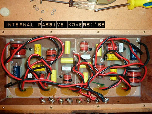
A passive crossover can operate between an amplifier’s output and drivers, using electrical components to shape the signals at that point. The photo shows a physical passive crossover assembly from a Linn Isobarik loudspeaker. An active crossover can divide the signal before separate power amplifier channels drive the different units. Genelec’s technical introduction describes one such type of arrangement. In a compact powered system, all the pieces can be inside what you experience as a single cabinet. The important question about the arrangement is where the division occurs relative to the amplifiers.
A speaker being connected to mains or to an internal battery is not enough to identify the placement of every crossover in the system. A cabinet might contain amplification and still have some other division downstream of a particular amplifier. A product can also have a separate subwoofer arrangement that supplies low sound under a different set of terms. Consult the documentation for the signal path if it matters. The schematic order of stages can have more practical value than looking through a hole in the cabinet for something resembling the pictured assembly.
The parts in a passive crossover interact with a load whose properties can vary with frequency. In an active arrangement the filtering and power stages can be addressed separately, which gives designers some different choices. These are tradeoffs about the whole system. They are not reasons to assume a passive speaker cannot produce even sound, or that two amplifiers immediately make an active setup accurate. Knowing which architecture you have is a way to understand which observations could distinguish the causes of a problem.
A different kind of listening check involves two matching speakers at the same distance. If a recording of speech has almost no crisp sounds on one side and sounds ordinary on the other, you can note where the difference stays as you change which recording channel supplies each intact speaker. Follow the system’s instructions before making any connection changes; often the source can swap channels without touching cables. A difference that follows the signal across speakers is evidence of a different kind from one confined to the same speaker. Neither outcome identifies a failed crossover part on its own. It helps establish what is worth asking a service technician to inspect.
A result often has a position as well as a level
Move a little sideways relative to the cabinet and one driver can become farther away relative to the other. Turn the whole cabinet and you may look more directly toward one part of its radiation pattern than before. In a room you also experience sound reflected off walls, floor and ceiling. It is easy to produce a difference between two listening positions without changing anything in the recording. A result you noticed at an extreme angle is worth recording. It cannot by itself stand for the response at the intended seat.
Try comparing positions at a comfortable level with the same recording and the same settings. Use a relatively steady passage, or repeat a small section so that the source is not changing during the comparison. Say whether there was a change in the character of a voice, an isolated note or a broad range. Do not take this as a way to isolate a crossover’s measured performance from the room. It gives you a disciplined description of a result. Proper response measurements need a suitable method that can deal with reflections and position more explicitly.
If two systems disagree in one room, hold the basic conditions close enough for the comparison to mean something. One could seem preferable because it occupies a position with a substantially different reflection nearby. Moving a cabinet can change how low sounds reach the listener quite apart from the behavior of the drivers at their crossover. An observation made at one seat is valuable for that seat. Before calling it typical of the design, see whether it persists at other appropriate positions and in settings comparable to those for which the system was intended.
The next time a voice seems to belong to one place in front of the cabinet, give the division hidden behind it a little attention. Some of the overlap is doing work you would only notice if it were less successful. The interesting question is not which driver can claim the entire voice, but what part of the signal reaches each, what sound it makes from that part and what both sounds become where you hear them.