What a Laptop Heat Pipe Carries
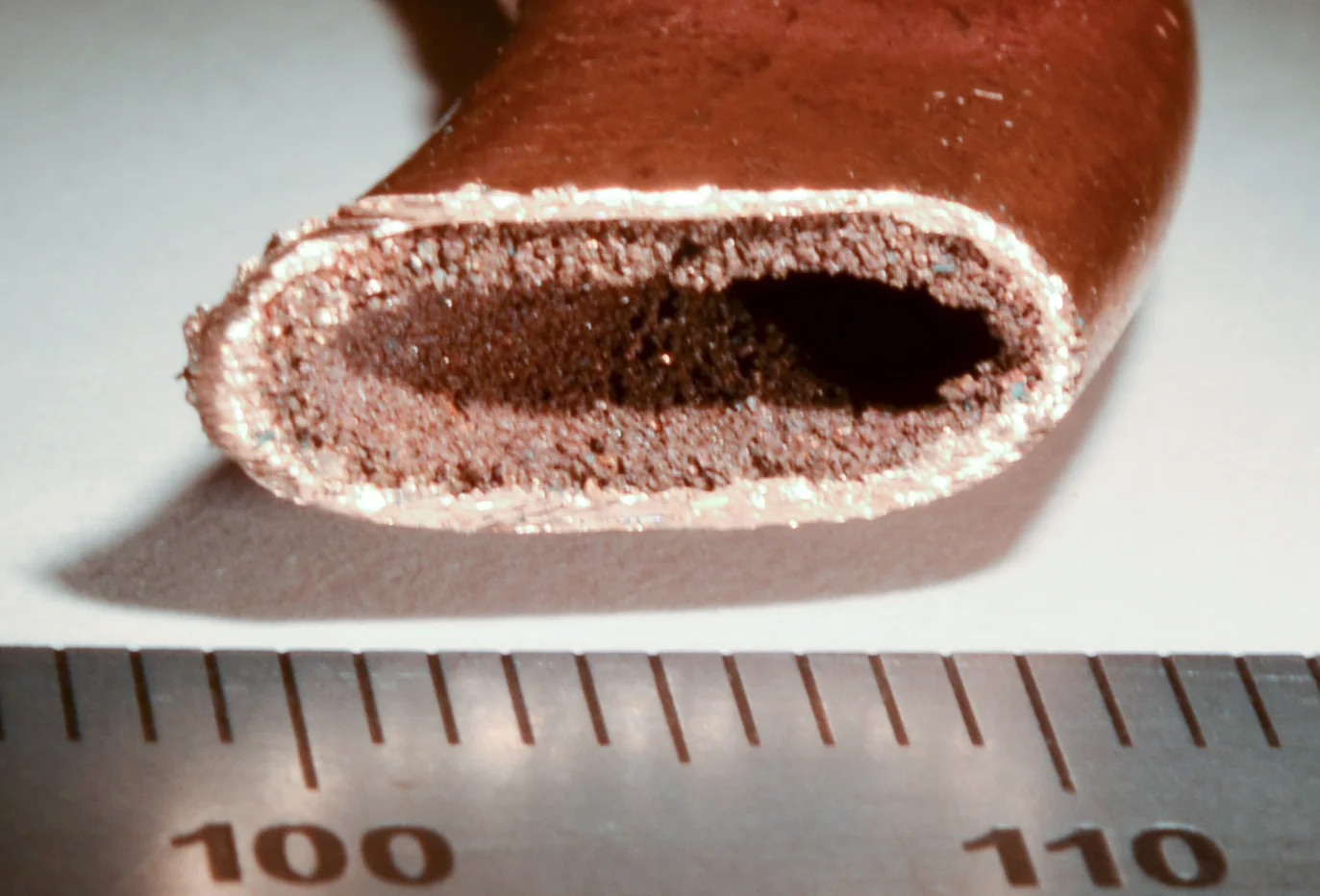
A cut end shows a hollow centre and a porous inner layer. Inside an intact pipe, evaporation and condensation move energy toward the fins while liquid finds its way back.
In this story 5 sections
The open end of the copper-coloured part in Epbernard’s photograph looks like a narrow tunnel. The hollow has a flatter profile than one might expect from the word pipe. Around the edge of it is a rough layer, distinguishable from the smoother outer wall. A ruler shows that the whole section is only millimetres across. The source identifies it as a cut section of a heat pipe from an HP laptop made in 2008. An intact pipe does its work sealed, so the image is evidence of the layout, rather than a picture of the device in operation.
It takes a surprising amount of interpretation to look at that hollow and understand what the laptop gets from it. On the board, a component that releases heat may sit some distance from a vent. The best place to put a large surface in moving air is not always directly on top of the source. A slender device needs a way to carry energy around that spatial problem. A heat pipe does so partly with its metal, and to a large degree through what happens to a small amount of working fluid inside it. The rough edge and the open centre each have a separate part to play.
Start at the part that needs cooling
An ordinary conduction route already connects several things inside a laptop. Heat moves from the chip through its package and the contact materials into a plate or related assembly. If two apparently flat surfaces meet, only parts of them touch closely enough to transfer heat effectively. A specified interface material can help the installation by filling small gaps. That is an earlier stage than the action inside the pipe. If the heat cannot get into the assembly efficiently, moving energy well from one end of the pipe to another will not fix the first gap.
Now consider where that solid plate should send the energy. A wide chunk of conductive metal can carry it but competes for thickness and room. A heat pipe offers a narrow package that can bend through space within its design limits. The evaporator is the region receiving heat. The condenser is the region from which heat can be transferred onward. Other parts of the tube connect the two. Those words describe what happens in each region under ordinary use. They are less useful if taken as proof that one fixed little cap at each end does all the work.
NASA's Spinoff account describes miniature heat pipes designed to move heat from a compact source toward air flow in notebook computers. The example makes the packaging problem concrete. The air that can remove heat may have a good path only near an edge. A layout aimed solely at a short distance from chip to cooler might overlook that edge. For the whole machine, the distance to a useful heat exchanger matters as much as the first distance from the chip to nearby metal.
A loop without a mechanical pump
At the hot part of the sealed tube, some working liquid takes up energy and evaporates. The vapour can move through the open interior toward cooler parts. There it can condense. The return to liquid releases energy into the pipe wall at the cooler region, where the cooler's fins or another load can take it. The metal carries some heat directly as well, but the change of phase lets the moving vapour transport energy particularly effectively for the available cross section.
It is useful to follow one round trip in imagination. Energy enters at the evaporation region while liquid is close enough to take it up. Vapour moves through the central space. When it condenses, liquid now accumulates elsewhere. If the story ended there, the area near the heat source could run short of fluid. A wick structure inside the tube supports the other leg of the trip. Capillary action in the narrow spaces helps draw liquid back toward the region that needs it. This path and the more open path for vapour can sit very close together without being the same path.
The loop is passive in the sense that it does not require a motor to circulate the working fluid in an ordinary heat pipe. The temperature difference and the materials arranged inside the tube help establish movement. A separate fan in a laptop may well need electricity. It works on air around the heat exchanger rather than on the liquid returning in the pipe. A working cooling assembly can thus contain an active piece and a passive one, each with a different medium and a different job.
The rough edge is a functional surface
The cut section makes it possible to see the space inside from one end. The lining is more textured than the outside and narrows the part left open. Designs can make capillary structures in several ways. NASA's thermal control overview describes grooved examples, and its account of a miniature notebook cooler discusses a porous metal wick. The photograph can support the broad distinction between a lining and a passage. It doesn't establish all the particulars of its material, its original fluid or the pressure inside the sealed part when new. It is not necessary to guess those details to understand why there are two textures in the section.
A simple comparison is the way water can rise a short way into a narrow space between wettable surfaces. In a porous structure there are many narrow spaces through which the liquid can travel. Small spaces can help create the force drawing it, while very fine passages can also resist substantial flow. Designers balance those properties for the intended job, including how much liquid has to move and how far. Gravity can help or oppose part of the return depending on orientation. A useful design has to supply the needed return across expected conditions rather than relying on every tube being held one convenient way.
The open area makes a different demand. The vapour needs room to move through with relatively little obstruction. A flattened tube has to fit into the machine without losing too much of that room or disturbing the structure that returns liquid. That is one reason to treat the profile as part of a manufactured system. Crushing an arbitrary round tube flat would not make it equivalent to a carefully made heat pipe. The visible edge, open passage and broad flattened face have to continue to perform their tasks together.
The cooler still needs somewhere to give the energy away
At the far end the pipe is part of a larger path again. A set of thin fins can make a much larger area for contact with air than the strip of pipe alone. Air moved through the stack takes energy out of the assembly, then leaves through a vent or another route. This is separate from getting heat from the chip into the pipe; a restriction near the fins affects the final stage of the same process. The fan can be turning while something about the air path still prevents that stage from doing its usual work.
A warm region near the fins can be consistent with heat being carried away from the component. A warm case can also receive heat through incidental contact elsewhere. A single touch or a single temperature reading is rarely enough to identify a failing part. To understand a reported change, consider the workload and ambient conditions, whether there is air leaving the vent, and how the system behaves over time. The chip can temporarily run hotter before a fan accelerates without that moment alone identifying a failure in the pipe.
A thermal design has a capacity. If the rate of input rises beyond what the assembly can move and reject in its current conditions, temperatures can continue to rise. Different limiting conditions can produce a broadly similar effect from outside. A picture of the pipe's section is useful in explaining why getting the wick, fluid and passage right matters, but cannot replace evidence from the machine when assessing a particular cooling problem.
Temperature and the rate of heat transfer are separate quantities. Two laptop assemblies can hold their chips at similar temperatures while moving quite different amounts of heat, because they are operating at different loads or with different air temperatures. Conversely, two machines asked to do the same work can settle at different temperatures. To compare one path with another, a useful observation identifies the load and the surrounding conditions before comparing where the temperatures have settled.
Why the centre was left hollow
Return to the narrow opening in the photograph after tracing the path through the entire machine. At the source there are solids in contact. In the pipe there are two routes in opposite directions for different states of the same substance. At the fins another solid carries heat to flowing air. The open centre and porous edge help explain why the pipe belongs between those two solid assemblies. The centre does not have to be packed solid with an especially good conductor in order to do useful work. The space is used by vapour on its way toward a cooler place.
Seeing the pipe in section also shows why most of its work remains easy to overlook in an assembled laptop. A thin lid and a row of vents suggest where the air leaves; they offer little view of the stages bringing energy there. The cut end gives one of those stages a visible form. The hollow lets the working fluid depart in one state, and the fine structure near the wall lets it return in the other.