The Trigger That Holds a Wave Still
The signal entering an oscilloscope keeps changing even when the trace looks fixed. A trigger gives each view the same reference point and helps catch events that only happen once.
In this story 5 sections
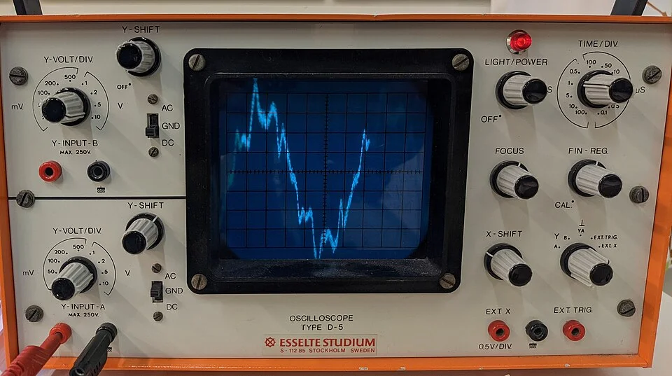
The old Esselte oscilloscope in the photograph has a glowing blue line and several rows of knobs. In the middle of the face is a regular grid. Against it the line appears to occupy a definite place. A falling section of the trace seems to belong in this part of the glass and a rising section in that part. The photograph shows neither electrical motion at an input nor a circuit drawing each line separately. It shows one view of a measurement after the instrument has supplied axes and a reference for time.
That reference is worth taking apart because it explains some apparently contradictory experiences with oscilloscopes. One signal can make a trace that seems to drift sideways. The same signal, with an appropriate trigger, can occupy one place so steadily that it looks like an ordinary diagram. Meanwhile, a signal that rarely changes can require a different kind of attention: the important part of it arrives occasionally, with no way to tell by eye when to look. The trigger helps in both cases by setting a condition under which a slice of time should be shown.
Decide where a drawing can begin
The vertical position of a normal voltage trace relates to the input voltage. The horizontal position relates to time. Set a faster rate across the grid and less time fits across the same width; a particular interval can then take up more room. Set a vertical scale to show more volts per division and the same variation uses less height. These are ways of saying how much goes on the page. They leave one question open: which part of the incoming signal should count as the start or reference point?
Suppose a signal follows a smooth hill and valley once per cycle. A first sweep beginning at the foot of a rising hill puts the top somewhere to the right. A second sweep beginning at the top puts it farther left. Repeat with starts scattered throughout the cycle and the lines on the screen bear very little resemblance to the repeated signal. No part of the electrical event had to change for the drawing to become difficult to read. The instrument has changed the alignment of successive views.
One way of picturing the fix is to line up several prints of a song recording. Say each print starts in a different place, but every print contains a drum strike of a certain shape. Find that strike and align it vertically on every page. The notes after it will move into much better agreement if it is the same performance. It matters exactly which strike you use. A trigger does the equivalent of agreeing on the landmark before drawing or recording the next view. The signal is free to keep running before and after it.
Level and slope are different instructions
Imagine a demonstration signal that rises from one volt to three and falls back again. Somewhere on the ascent it passes through two volts. Somewhere on the way down it passes through two volts again. The chosen trigger level might be two volts, but level alone does not settle which of those two events should be the reference. For a common edge trigger, the slope control gives the next part of the instruction. A rising edge asks for the crossing from below the level; a falling edge asks for the crossing from above.
Set the source to that same demonstration signal and either choice can steady the display. The trace will line up differently, because the two events happen in different parts of the cycle. Set the threshold above the maximum of the signal and there is no qualifying crossing. On some instrument settings a sweep or update may appear anyway, without the same relationship to the signal. On others the instrument can wait for an event that does not happen. An unsteady or old view can thus be a clue to a condition set on the instrument rather than a new fact about the source.
Real transitions can have noise or ripple. A crossing that appeared to occur just once in an ideal sketch might have several candidates when viewed close up. The precise response depends on the instrument and its settings. A useful habit is to look at the size and shape of the transition relative to the chosen level. A condition that sits very close to an ordinary noisy plateau can mean something different from one in the middle of a clear rise. The figure of two volts is only a thought experiment; its virtue is that the crossing is easy to place between the imagined limits.
The reference does not have to be the thing on display
A scope can use one input to decide where a capture starts and show another against the same time axis. Picture a small teaching demonstration with a timing reference and a separate output. The rising edge of the reference provides a landmark. With the display following that landmark, the viewer can look for a small delay until the output responds. Triggering on the output instead could place that output in a very stable position while giving a less direct view of how it follows the reference. The choice depends on the question. If you want to know what happened after the clock edge, identify the clock edge first.
This distinction explains why a still display need not mean every trace is fixed in relation to every other one. A reference can repeat reliably while a second input varies for reasons of its own. Relative motion on the screen can then be the information sought. Alternately, two signals can fall into a stable relationship which makes the delay between features easier to read. In either case it helps to know which event the instrument treated as the anchor. Otherwise an orderly screen can give a false impression that the chosen point in time was inherent in the signal being examined.
This makes settings part of a measurement record. A practical screenshot benefits from notes identifying time per division, the channels and the trigger source and condition. A colleague may be able to see a small feature without those notes, but will have a much harder time deciding when it took place or recreating the observation. A single cropped screen export can communicate much less than the operator assumes.
Keep a little of the past
An analog and a digital oscilloscope can make pictures of a repeated event in different ways. In a traditional analog scope a sweep begins and the trace is drawn as the signal proceeds; some instruments include a short delay in the vertical path so the immediate start of an event can be seen. A digital oscilloscope can keep updating a buffer of readings before the selected trigger occurs. It can preserve some of that recent past and some time after the event in one acquisition. The trigger is then a point inside the record, rather than necessarily the leftmost point of the picture.
A long stretch before a fault is valuable when the thing that made it happen lies upstream in time. Suppose a demonstration signal usually delivers a rectangular pulse of a certain duration but sometimes gives an unusually short pulse. A scope with a suitable pulse trigger can be asked to capture the exception. If its acquisition includes enough earlier time and the relevant second signal is recorded too, the earlier part may show whether another transition often preceded it. It does not, by itself, prove that one transition caused the other. It gives the operator a sensible observation to investigate.
The same arrangement can preserve a single intended event. Think of watching one brief pulse produced during a laboratory demonstration with a known source. The pulse will not produce the recurring sweep that makes a trace readily visible on some analog displays. A digital acquisition waiting for a matching condition can keep those samples on screen after the signal has returned to its previous value. Someone can examine the rise and fall afterward. The limits still matter: too little recording time can leave it incomplete; inadequate sampling can miss or misrepresent detail. A successful trigger supplies the occasion to record. It does not improve the underlying measurements.
Read the grid and the conditions together
Look again at the Esselte photograph. The regular vertical and horizontal lines give the glowing trace a place to be, and the control panel hints at decisions invisible in a cropped picture of the grid. The camera caught the brightness of the display at one moment. It cannot establish a full account of which conditions the instrument used, which exact source was connected or how the trace would behave if the operator moved one control. That is why a comparison made on a known demonstration source can be more informative than guessing from a good-looking photograph.
The next time a trace crawls or sits still, see whether the time reference explains its behaviour before drawing a conclusion about the waveform. Is the instrument agreeing to begin on the upward crossing of a level, on another channel's edge or on a rarer event selected for a single capture? The answer gives meaning to the horizontal positions on the screen. A trigger does not hold the underlying signal still. It holds the observer's reference steady enough for differences in the signal to be seen.