The Fourth Wire on a Cooling Fan
A four-wire fan can receive a speed command and report its actual pace separately. Counting revolutions tells a different story from measuring the air that moves through a case.
In this story 5 sections
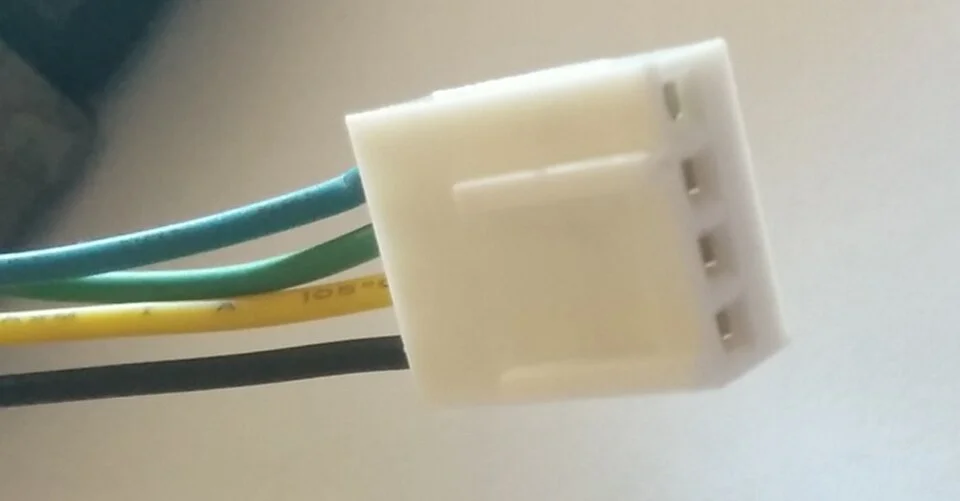
A computer can ask a fan to slow down and still need to know whether it actually did. Looking through a grille may show that the blades are moving. It will not settle the question of their speed, let alone the question of how much cooler air reaches a particular component. The small plug photographed here is a better place to begin: it is an example of the connection through which a fan can receive power, hear a command and send information back.
Noctua's technical paper describes four-pin fans with separate connections for supply, ground, speed feedback and a PWM control signal. The document sets out the requirements for its own designs. It is not an instruction to connect arbitrary wires by colour. The useful point is the separation of tasks. A device asking for a certain level of cooling and a fan reporting how it turns do not have to use the same signal.
A command is not a measurement
PWM means pulse-width modulation. In a simplified description, a control signal switches between two levels during each repeated period. Change the part of the period spent in one of those levels and you change its duty cycle. In an ordinary four-wire fan arrangement, the fan continues to receive power on its supply connection and interprets the varying control signal separately. The signal is not simply the supply switching off for part of the time in the model described by Noctua.
Suppose a fictional controller requests forty percent duty cycle. This is a statement about the signal. It does not by itself show that a particular fan reaches forty percent of its maximum rotational speed. Use the fan's specifications for the relation between those values if it matters. The shape of the response can differ among designs, and the behaviour at very low commands can have a special case. A graph that connects every possible percentage to a straight speed line needs evidence other than the similarity of their units.
Starting from rest is a useful example. A rotor already turning may continue at a condition where it would not confidently start in another situation. Some fan models implement their own behaviour at the lower end of their control range. It is sensible to check the model rather than expect zero command to mean the same physical state on every fan. The control panel's setting is an intention expressed in one interface. The rotor and its electronics are the parts tasked with carrying it out.
The beat that comes back
A tachometer signal can help a controller tell whether the rotor turns and estimate how quickly. Noctua gives an example of two output cycles per revolution for the fans described in its white paper. If a compatible measuring system sees forty such cycles per second, two per turn implies twenty turns per second, or 1,200 revolutions per minute. That arithmetic is illustrative; the cycles per revolution have to be taken from the actual fan specification. Counting the wire or relying on its colour will not establish the conversion.
Separating feedback from the command has practical value. A log might show a constant request while the feedback stops. That could mean the rotor stopped or that the measurement path failed. A rising request accompanied by nearly unchanged speed might mean the fan has reached a limit, the chosen settings are not being applied as intended or a reading is unreliable. Separate data channels invite better questions. They do not diagnose the hardware by themselves.
There is also a difference between a zero reading and a missing reading. A system could treat the absence of fresh pulses as evidence that no rotation is being detected. It could be unable to monitor that connection at all. The difference is relevant if the value is used in deciding how to investigate a cooling complaint. An explicit unavailable display is often more honest than a number where no compatible measurement was made.
Speed does not show where the air goes
The tachometer concerns rotation. The machine owner may care instead about temperature, noise or air moving through a narrow enclosure. A fan rotating at the expected speed can be mounted so its flow does not take the route a builder intended. An obstructed intake, a poorly seated panel or a different restriction elsewhere can change the airflow without changing the nominal speed much. Before comparing two systems by RPM, identify what quantity the comparison is supposed to explain.
A simple illustration is a fan near a restrictive grille. Turning it at the same pace in open air and in an assembly does not promise the same volume of air moves past a sensor or heat sink. A temperature reading also depends on workload, ambient conditions and the location that is monitored. The proper comparison holds those conditions as steady as the question allows. A computer that finished a heavy job in one test and sat idle in another has provided two different circumstances, however similar the speed display looked.
Noise has its own path. The same rotor speed may be more noticeable behind a panel or near a surface that vibrates, or may sound different to somebody sitting farther away. This helps explain why an apparent numerical improvement can miss what a person was trying to fix. Notice whether the symptom concerns cooling, an unexpected sound or a warning about missing feedback. Investigating each in the same way would waste evidence supplied by the symptom.
A nearly matching plug is only a first clue
A cooling connector can look familiar across machines while the supported voltage, control modes and pin assignments differ. The manufacturer's documentation for the fan and controller matters more than a wire colour in an unrelated photo. Even a close look at the four-position plug tells us only so much. It makes four contacts plausible and gives an idea of mechanical orientation; it does not establish that any particular header is appropriate for the fan.
A useful parts comparison records the complete model alongside the connector. Check what range the controller supports, what fan signals it can read and whether the intended operation is documented. A controller can offer modes with different expectations about how a fan is varied. A label in a setup screen can be more useful once its meaning is known from official product information. Guessing from where the wires run can miss a difference between what the hardware supplies and what the selected mode does.
If the issue appeared after a replacement, describe both models and which readings changed. A new fan being heard but producing no speed display has not necessarily failed to cool. A fan displaying one plausible number has not necessarily been connected or mounted correctly. A technician can compare the reported speed with the operating condition, review the installation and decide which explanation is supported. It helps to present the hardware change and the new symptom as distinct observations before joining them into a diagnosis.
Read the sequence at the moment the problem occurs
Sampling affects the apparent accuracy of the speed display. In the earlier two-pulse example, a short counting window can contain very few events if the rotor turns slowly. A difference of one count can have a conspicuous effect on the displayed number. A longer window offers a more stable estimate while making it slower to recognise an actual change. Measuring the time between pulses is a different approach. Which interpretation matters depends on how the controller records and presents feedback. The decimal places used by one monitoring interface do not establish its measurement resolution by themselves.
A second example separates two instruction paths. Suppose a board selects the requested speed according to a heat sensor in one operating mode and follows a fixed setting in another. In both modes the fan's tachometer still concerns the turning rotor. When a temperature rises without a corresponding change in request, that observation raises a question about the control logic or selected mode before it raises one about the motor. Conversely, if a different request is issued and repeated but the rotor never responds, the request and feedback provide a narrower interval to investigate. The same number of wires supports both comparisons.
A good report collects the request, the feedback and the relevant temperature over the same interval. If the request rises after the temperature rises and the speed follows later, the sequence says something different from a single high temperature and high speed captured after the event. The reported data also have limits. Polling can smooth or skip short changes. A few consistent, dated observations with the workload described can be more useful than several instant readings copied at unrelated moments.
The displayed label should identify which fan is being measured. It is easy to compare a processor temperature with the speed of a case fan when several headers appear on the same dashboard. The apparent delay might then belong to an unrelated control policy.
There is a fourth thing to ask after reading those values: is the cooling path itself as intended? The fan may be working, the measurement may be telling the truth and the system may still be moving air past the wrong place. That is the value of keeping command, rotor speed and thermal conditions separate. The fourth wire in this type of design gives the first of those jobs its own channel. It does not turn any one number into an answer for the entire machine.