The Filter a Screen Looks Through
Turn a polarizing lens in front of a liquid crystal display and a bright image can nearly disappear. The experiment reveals what an LCD does to light before it reaches your eyes.
In this story 5 sections
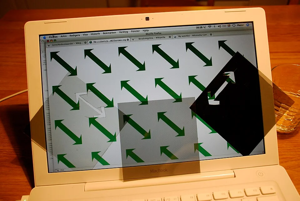
The laptop in Pieter Kuiper’s photograph is lit. Green arrows repeat across the display. Yet a sheet held up over it is so dark that the pattern behind that part almost disappears. A second sheet admits much more of the light from the same image. The camera was pointed at one display, at one moment, with the same screen settings underneath both pieces of material. What differs is the relation between the direction the screen's light takes as it leaves and the direction that each sheet will pass.
A simple version of the photograph can happen when someone in polarizing sunglasses looks down at a display. In one position the text is readable. Turn the display or tilt the head far enough and the image may become harder to read. The display did not lower its brightness in response to the sunglasses. It had been sending light with a preferred orientation all along. The added lens is deciding how much gets through. The effect is easiest to understand by treating the panel as several optical layers, whose different contributions a normal picture hides.
Light has a direction besides the one it travels in
A beam can travel toward a reader while its electric field oscillates across that direction of travel. Imagine looking straight into the beam. There are many ways to draw a line across the view: vertical, horizontal and every slope between them. Those are possible orientations for parts of the light in the beam. In a simple picture of linearly polarized light the field oscillates along one such line. The orientation can be called the axis of polarization. The beam is still heading toward the reader regardless of which line describes that oscillation.
A sheet polarizer admits the field component along one preferred direction and strongly attenuates the perpendicular component. It does not have to send the light on a new path to do so. If already polarized light reaches it with its orientation aligned to the sheet’s preferred axis, much of that light can get through. Rotate the sheet through a quarter turn and a good idealized polarizer would pass none of it. At intermediate positions a portion is transmitted. In the actual photograph light can also be reflected by the sheet and surrounding room, and a real device will not necessarily reach perfect extinction. That doesn't erase the large difference between the axes.
An everyday comparison is to use two pieces of linear polarizing film in front of an ordinary light. Rotating both pieces together doesn't change how they sit with respect to each other. Keep one still and rotate the other, and they can range from parallel to crossed. The first sheet makes the second one easier to understand: it turns light without a single preferred orientation into a source having one. An LCD already has a polarizing sheet near its front. This is why a separate card of the same kind can reveal something about the light coming out of the screen without help from a lamp and a second card.
What the crystal does in between
Consider one conventional twisted nematic arrangement, as illustrated in Florida State University's optics material. Light enters from behind through a first polarizer. Liquid crystal molecules between the glass surfaces tend to be oriented with a particular pattern in the cell. Under one condition their change in orientation through the thickness of the cell makes the light's polarization follow a twist. A second polarizer, set across the first, can pass the resulting orientation. Even though the two sheets alone would block the light in this arrangement, the liquid crystal helps it reach the other side.
The behaviour changes when a voltage across the cell reorients the liquid crystal. If that twist is sufficiently reduced, much less of the light has the orientation needed to pass the second filter. A segment that was clear can look dark. Control enough small areas independently and it becomes possible to make letters, shapes and ultimately detailed pictures. The light source may stay on while those changes take place. This is the important difference between asking the light source to pulse brighter and arranging for a selected region to let more of the existing light through.
The two positions are a useful drawing of one family of displays, not a universal description of which voltage makes every LCD dark. Different panel modes arrange molecules, driving fields and other films differently. Some designs begin from a state that appears dark with no drive at the pixel. Intermediate settings allow shades, and the optical response varies with angle. The point shared by many of these screens is that the changes in the material can be turned into a change in brightness by the polarizing system. It would be much harder to see the intended dark and light areas if that system simply let both states through.
What happens to red, green and blue?
A familiar desktop image contains colors and fine variations in brightness within those colors. On a common kind of color LCD, carefully arranged filters supply red, green and blue subpixels. Each subpixel has a way to vary the amount of light that passes in that part of the array. A particular shade is the visual result of several neighbours working at once, seen from a distance where the eye treats them as one small point in the picture. The polarizers contribute to control over how bright those individual components appear; they are doing something different from the filters that select a band of colors.
The photograph shows those jobs at once. The bright areas can still show green arrows. Outside light in the room can also reach the surface and reflect off it. A dark polarizing card over the image does not have to find the green pixels electronically or change the software. It applies an additional test to the light already leaving that part of the display. Where the card and panel have substantially crossed axes, the green and the bright field behind them can both become difficult to see. The color picture is still there for a person looking past the perimeter of the card.
For another example, imagine reading white lettering on a black background instead of green arrows on white. When much of the light is blocked by an added polarizer, it is primarily the light from the lettering that has farther to fall. The dark spaces were already dark by comparison, though room reflections might still be visible on both. What disappears from the reader's point of view is the contrast between useful parts of the image. That is why turning up the screen can make a modest difference at one angle yet be an unsatisfying fix when the added filter is near the strongest blocking position.
Turning on the screen is a separate test
A black-looking display may be off, or it may be on with low contrast or be giving off light that cannot reach a viewer through something placed in front of it. A change with orientation is a clue that can help sort those cases. Try looking at the same region directly at an ordinary reading angle, without a dark lens. The display that looks fine to bare eyes but fades at a particular rotation of polarizing film is behaving differently from a screen that shows no view at any angle. The comparison requires no changes to panel settings and no disassembly.
This observation matters outside a demonstration at a table. Suppose someone is using a phone outdoors and rotates the phone from upright to landscape to see a map. The amount of glare may depend on the sun and other reflections. The sunglasses also shift relative to the phone's display. If the photo of the landscape is still readable but labels on the map look weak under those lenses, check the same content at a different rotation before assuming an app changed the labels. The effect will vary by phone and by eyewear; some screens manage the polarization reaching the viewer in ways that reduce differences with direction. Two displays that use liquid crystals do not have to react identically in that experiment.
Treat off-axis views separately. An LCD can appear different when examined from the side because light has taken a different path through the panel stack. An external filter adds its own orientation-dependent effect. Tilting a screen in a single move can change both variables. To identify the role of film more clearly, hold the angle to the panel steady and turn the film in its own plane. That is closer to asking one question rather than two at the same time.
Revisit the arrows
In Kuiper’s experiment, two pieces of film have clear arrow-shaped holes showing their intended axes against the arrows on the screen. The comparison is still readable if you ignore the exact graphics. One patch leaves the image relatively light; another takes a large part of its light away without turning the laptop off. A second object placed in front of a screen is able to reveal a property the display has been using inside all along.
The orientation was invisible when the only thing in front of a well-lit panel was the reader's eye. The extra sheet makes it observable. It also clarifies what a panel's brightness control cannot explain. An LCD is not a bare lamp behind an image. A chain of layers decides which light survives each part of the trip. The striking part of the experiment is that one more layer, held outside the computer, can change the visible result without changing a single pixel value.